Chapter 25
Retinal Prosthesis (“Bionic Eye”)
In the late 1960’s, Potts and Inoue demonstrated the use of a contact lens as a stimulating electrode to evoke an electrically elicited response (EER) of the visual system of rats and humans.[1,2,3] Expounding upon their discovery, Knighton later specifically demonstrated the ability for inner retinal layers to be electrically stimulated to elicit an EER.[4,5] For a retinal prosthesis to be theoretically able to function, there must remain enough viable retinal cells to propagate an electrical signal through the inner retina and along the optic nerve and afferent visual pathway. As such, studies have demonstrated relatively good preservation of retinal inner nuclear and ganglion cells compared to photoreceptor loss in endstage retinitis pigmentosa and neovascular and non-neovascular age-related macular degeneration (AMD).[6,7,8] Further studies were undertaken, establishing the efficacy and safety of electrical stimulation of the retina[6,9,10] and led to the development of a more permanent implantable retinal prosthesis, starting with the ARGUS I and later the Argus II systems.[11,12,13,14,15,16,17] Argus II retinal prosthesis is the only retinal prosthesis currently FDA- approved in US. There is ongoing research in other epiretinal, subretinal, supra-choroidal, as well as cortical implants.
Potts AM, Inoue J, Buffum D. The electrically evoked response of the visual system (EER). Invest Ophthalmol. 1968.
Potts AM, Inoue J. The electrically evoked response (EER) of the visual system. II. Effect of adaptation and retinitis pigmentosa. Invest Ophthalmol. 1969.
Potts AM, Inoue J. The electrically evoked response of the visual system (EER). 3. Further contribution to the origin of the EER. Invest Ophthalmol. 1970.
Knighton RW. An electrically evoked slow potential of the frog’s retina. I. Properties of response. J Neurophysiol. 1975. doi:10.1152/jn.1975.38.1.185.
Knighton RW. An electrically evoked slow potential of the frog’s retina. II. Identification with PII component of electroretinogram. J Neurophysiol. 1975. doi:10.1152/jn.1975.38.1.198.
Stone JL, Barlow WE, Milam AH, Juan E, Milam AH. Morphometric Analysis of Macular Photoreceptors and Ganglion Cells in Retinas with Retinitis Pigmentosa. Arch Ophthalmol. 1992.
Kim SY, Sadda S, Pearlman J, et al. Morphometric analysis of the macula in eyes with disciform age-related macular degeneration. Retina. 2002. doi:10.1097/00006982-200208000-00012.
Kim SY, Sadda S, Humayun MS, De Juan E, Melia BM, Green WR. Morphometric analysis of the macula in eyes with geographic atrophy due to age-related macular degeneration. Retina. 2002. doi:10.1097/00006982-200208000-00011.
Stone JL, Barlow WE, Milam AH, Juan E, Milam AH. Morphometric Analysis of Macular Photoreceptors and Ganglion Cells in Retinas with Retinitis Pigmentosa. Arch Ophthalmol. 1992.
Humayun MS, Prince M, De Juan E, et al. Morphometric analysis of the extramacular retina from postmortem eyes with retinitis pigmentosa. Investig Ophthalmol Vis Sci. 1999.
Santos A, Humayun MS, De Juan E, et al. Preservation of the inner retina in retinitis pigmentosa:A morphometric analysis. Arch Ophthalmol. 1997. doi:10.1001/archopht.1997.01100150513011.
Humayun MS, Weiland JD, Fujii GY, et al. Visual perception in a blind subject with a chronic microelectronic retinal prosthesis. Vision Res. 2003. doi:10.1016/S0042-6989(03)00457-7.
Mahadevappa M, Weiland JD, Yanai D, Fine I, Greenberg RJ, Humayun MS. Perceptual thresholds and electrode impedance in three retinal prosthesis subjects. IEEE Trans Neural Syst Rehabil Eng. 2005. doi:10.1109/TNSRE.2005.848687.
Merrill DR, Bikson M, Jefferys JGR. Electrical stimulation of excitable tissue: Design of efficacious and safe protocols. J Neurosci Methods. 2005. doi:10.1016/j.jneumeth.2004.10.020.
Caspi A, Dorn JD, McClure KH, Humayun MS, Greenberg RJ, McMahon MJ. Feasibility study of a retinal prosthesis:Spatial vision with a 16-electrode implant. Arch Ophthalmol. 2009. doi:10.1001/archophthalmol.2009.20.
Humayun MS, Dorn JD, Da Cruz L, et al. Interim results from the international trial of second sight’s visual prosthesis. Ophthalmology. 2012. doi:10.1016/j.ophtha.2011.09.028.
Da Cruz L, Coley BF, Dorn J, et al. The Argus II epiretinal prosthesis system allows letter and word reading and long-term function in patients with profound vision loss. Br J Ophthalmol. 2013. doi:10.1136/bjophthalmol-2012-301525.
Ho AC, Humayun MS, Dorn JD, et al. Long-Term Results from an Epiretinal Prosthesis to Restore Sight to the Blind. Ophthalmology. 2015. doi:10.1016/j.ophtha.2015.04.032.
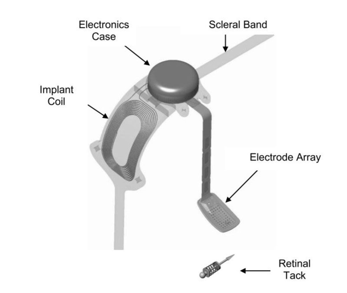
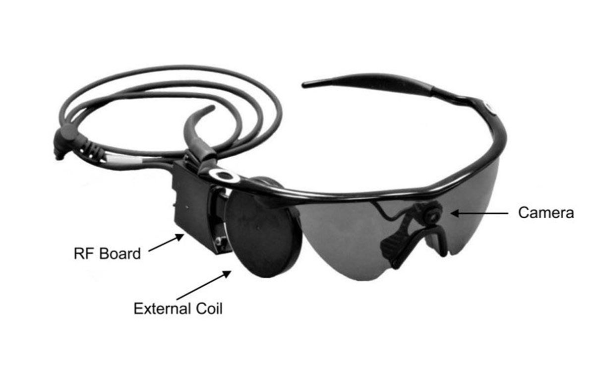
Argus II utilizes an external camera to capture and transform images into patterns of electrical stimuli that excite retinal neurons. The Argus II system consists of external wearable components and surgically implanted components (Figure 25.1). Spectacles with a camera capture the image and a video processing unit (VPU) then receives the image from the glasses (Figure 25.2). The VPU down-samples and processes the image into electrical stimulation data and sends it wirelessly to the electronics case via the receiving coil implanted on the globe. The electronics case generates the required pixelized stimulation output and sends it to the array of enabled platinum electrodes via a polymer cable with embedded wire conductors.
The surgically implanted components consist of the receiving coil and electronics case which are secured externally to the sclera. Subsequently a pars plana vitrectomy is performed and the 60-electrode array and the polymer cable are introduced into the vitreous cavity via a pars plana incision. The electrode array is positioned on the macula and secured with the use of a retinal tack.
- If the patient is phakic, the crystalline lens removal is performed to render the patient aphakic. The capsule needs to be removed after PPV is complete. If the patient is pseudophakic, no intervention is needed
- Perform the following standard beginning steps of an encircling scleral buckle (see Chapter 11.1 Rhegmatogenous REtinal Detachment - Scleral Buckle for details for steps i-iv below)
- Perform a 360-degree conjunctival peritomy at the limbus with relaxing incision nasally
- Dissect Tenon’s capsule
- Sling each of the four rectus muscles
- Inspect sclera for areas of thinning, staphyloma and anomalous vortex veins.
- Remove the ARGUS II implant from its sterile packaging. Please note that implant testing should occur at pre-set timepoints
- Use silicone tipped forceps when handling the electronic components of the implant. Using Nugent utility forceps, pass the silicone band with the coil under the lateral rectus muscle and continue to pull the band until the coil lies flat under the lateral rectus. Once in correct position, the electronics case adjacent to the coil should now lie flat in the superotemporal quadrant
Note
At this point, some surgeons prefer to protect the array by cutting the tip of a sterile glove, weaving a suture through the cut end like a purse string, inserting the array and tying the purse string suture with a slipknot
- Pass the remainder of the silicone band under each rectus muscle and join the band superonasally with a sleeve like a standard encircling buckle procedure (see Chapter 11.1 Rhegmatogenous Retinal Detachment- Scleral Buckle)
- Measure and suture the electronics case (Figure 25.3)
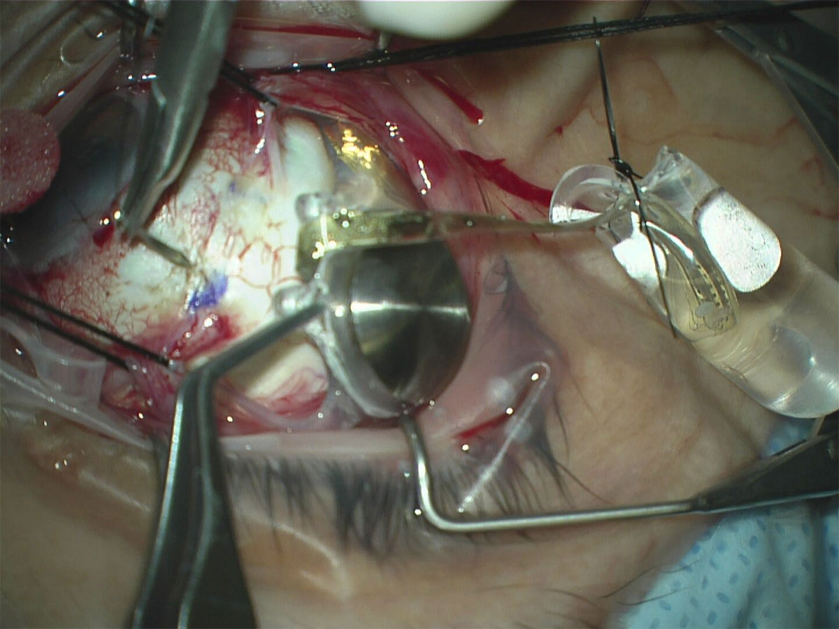
- Using calipers, measure and mark two points posterior from the limbus at 6.5 - 7.00 mm (using a nomogram based on the axial length of the eye) and 5.75 mm apart from each other in the superotemporal quadrant. These marks will be the location of the electronics case sutures.
- Align the case islets over the two scleral markings you just created
Note
When manipulating the electronics case or array, be very careful not to damage the small electronics. Use silicone-tipped forceps for this reason
- Using 5-0 Mersilene suture with a spatulated needle, anchor the case islets to the marked positions using partial thickness scleral bites and backing the needle through the islets. Tie with 3-1-1 a knot
- Measure and suture the coil
- Using calipers, measure and mark the same distance posterior from the limbus in the inferotemporal quadrant and in line with the islet of the coil
- Using 5-0 Mersilene suture with a spatulated needle, anchor the coil islet to the marked positions using partial thickness scleral bites and backing the needle through the islet. Tie with 3-1-1 a knot
- Using calipers, measure and mark the same distance posterior from the limbus in the inferotemporal quadrant and in line with the islet of the coil
- Secure the silicone band
- Secure the band in the inferonasal and superonasal quadrants as you would in a standard encircling scleral buckle procedure (see Chapter 11.1 Rhegmatogenous Retinal Detachment- Scleral Buckle)
- The band should be pulled snug but not tight; do not compress the globe, as would be for a buckling procedure
- Trim the excess silicone band tails
- Secure the band in the inferonasal and superonasal quadrants as you would in a standard encircling scleral buckle procedure (see Chapter 11.1 Rhegmatogenous Retinal Detachment- Scleral Buckle)
- Test the fit the array by gently and carefully reflecting it across the cornea. If it passes naturally through the center of the cornea, then it suggests the implant is anchored in good position
- Perform pars plana vitrectomy
- Proceed with standard PPV
Previous
Chapter 24 Stem Cell Therapy
Next
All rights reserved. No part of this publication which includes all images and diagrams may be reproduced, distributed, or transmitted in any form or by any means, including photocopying, recording, or other electronic or mechanical methods, without the prior written permission of the authors, except in the case of brief quotations embodied in critical reviews and certain other noncommercial uses permitted by copyright law.

Westmead Eye Manual
This invaluable open-source textbook for eye care professionals summarises the steps ophthalmologists need to perform when examining a patient.